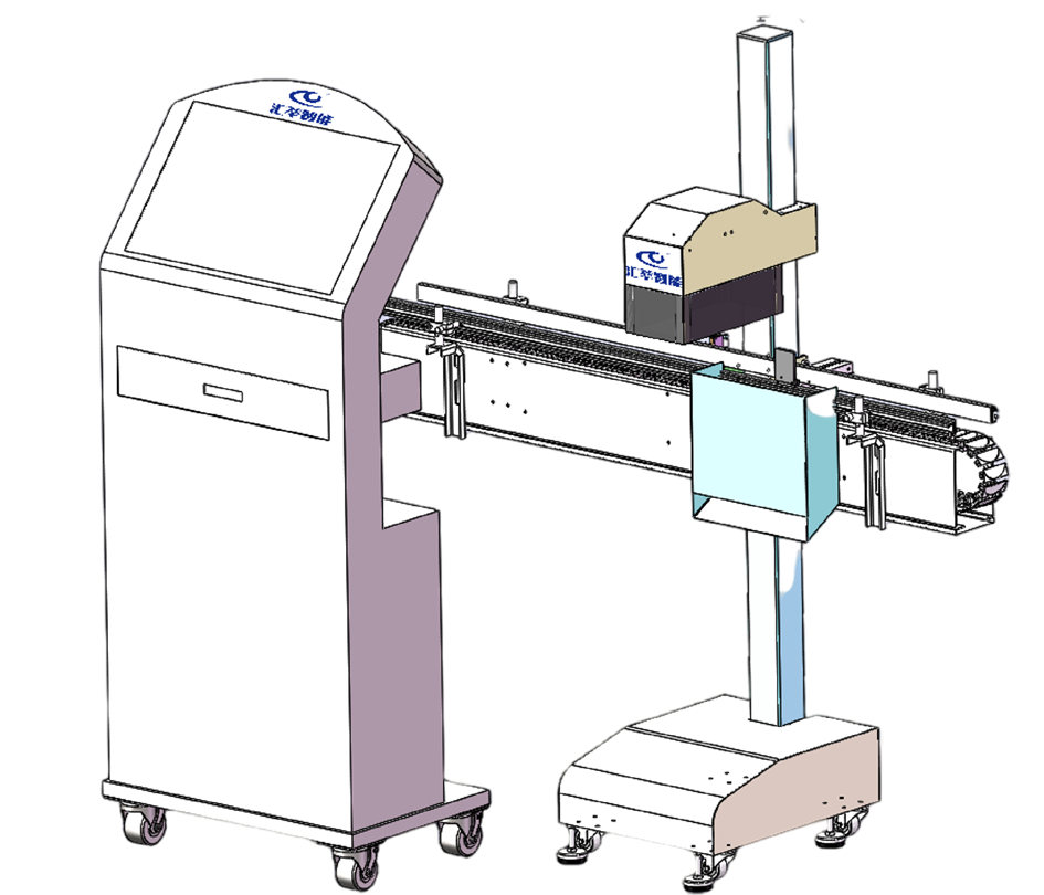
In today’s highly automated production environment, visual inspection systems serve as a key tool for quality control, playing a critical role. It can inspect products with extremely high precision and speed, ensuring that only products meeting standards can move on to the next process or be released to the market. However, to ensure that visual inspection systems achieves optimal inspection performance, precise tuning processes are indispensable.
This article delves deeply into the tuning process of visual inspection systems, detailing the key points and considerations for each step. Through a comprehensive analysis of the tuning process, one can learn how to properly fine-tune visual inspection systems, thereby improving the equipment’s detection accuracy and stability, reducing false positives and missed defects, and providing strong support for production quality in enterprises. Whether you are a professional in visual inspection systems building and optimization or a beginner, this article will offer you valuable reference and guidance.
1. Needs Analysis
- Engage in in-depth communication with the client to understand the characteristics of the product, including type, shape, size, material, etc.
- Clarify the specific goals of the inspection task, such as defect types (scratches, cracks, stains, etc.), dimensional accuracy (length, width, height), and positional accuracy.
- Determine the speed requirements of the inspection to match the pace of the production line.
- Understand the working environment conditions, such as temperature, humidity, dust, etc., and assess their impact on the equipment.
- Develop detailed inspection standards, including specific criteria for qualifying and disqualifying products.
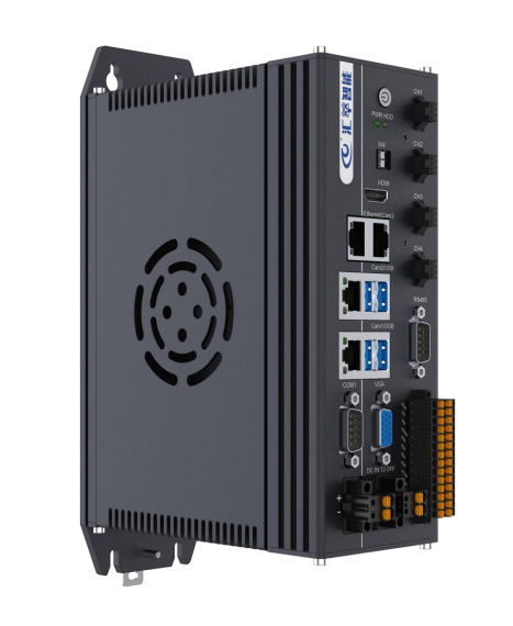
2. Hardware Selection and Installation
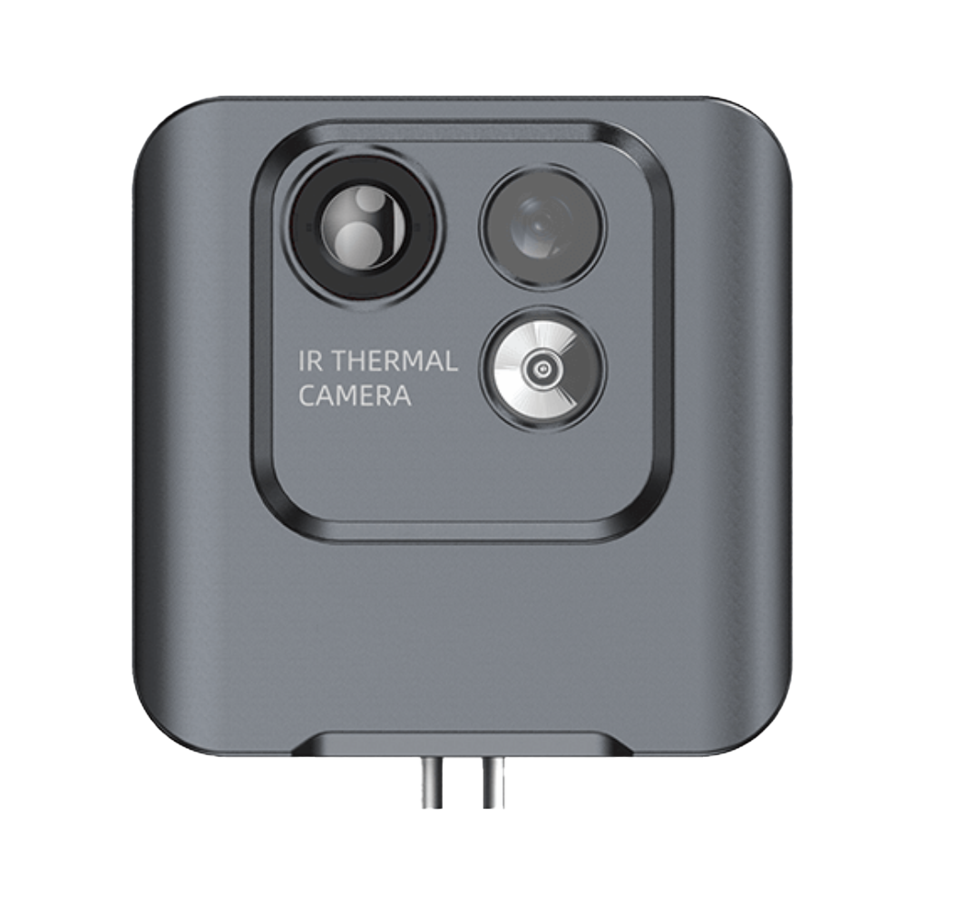
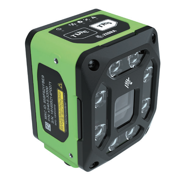
Camera Selection:
- Calculate the required camera resolution based on the size of the object to be inspected and the desired detection precision. Generally, higher precision requires higher camera resolution.
- Consider the production speed and choose a camera with the appropriate frame rate to ensure timely image capture.
- Choose a camera with suitable sensitivity (ISO) and dynamic range based on the lighting conditions of the working environment.
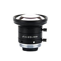
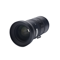
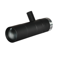
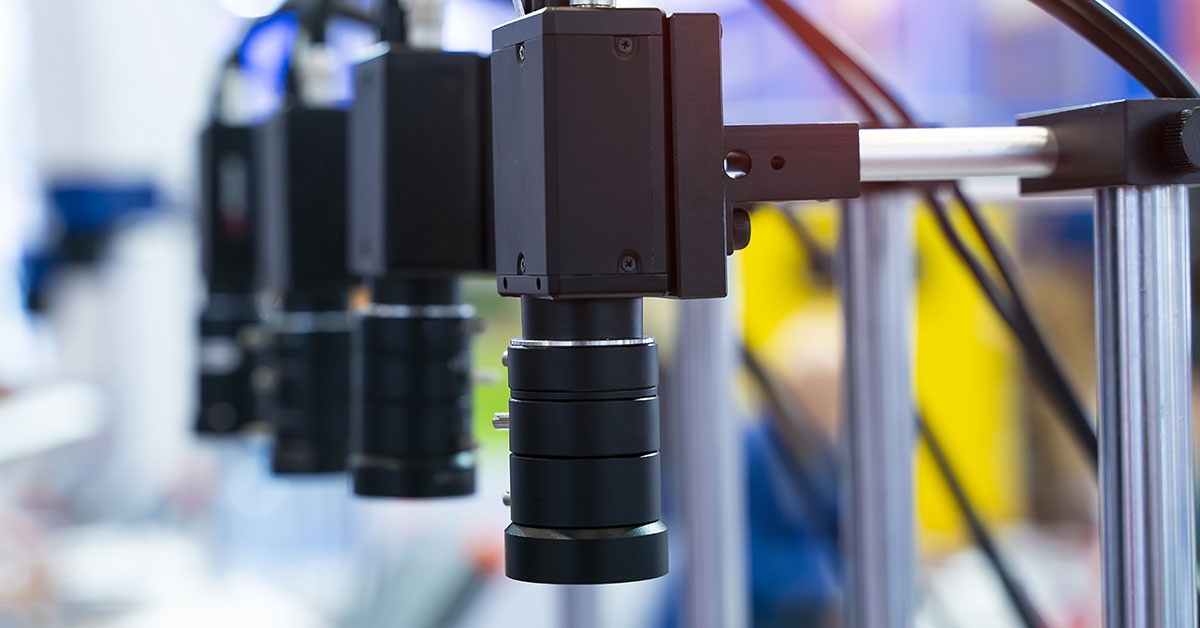
Lens Selection:
- Determine the focal length based on the size of the inspection area and the working distance, ensuring the object is captured completely and clearly.
- Consider distortion requirements and choose the appropriate lens type; for instance, a telecentric lens can reduce perspective distortion.
- Evaluate the lens aperture size to control depth of field and image brightness.
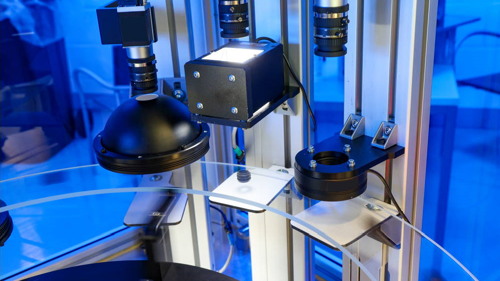
Lighting Selection:
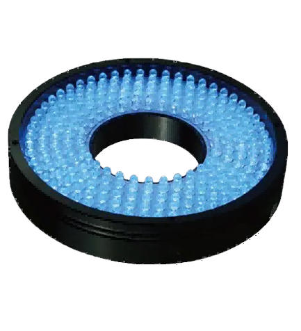
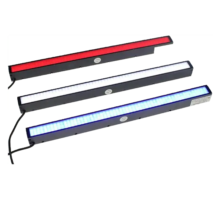
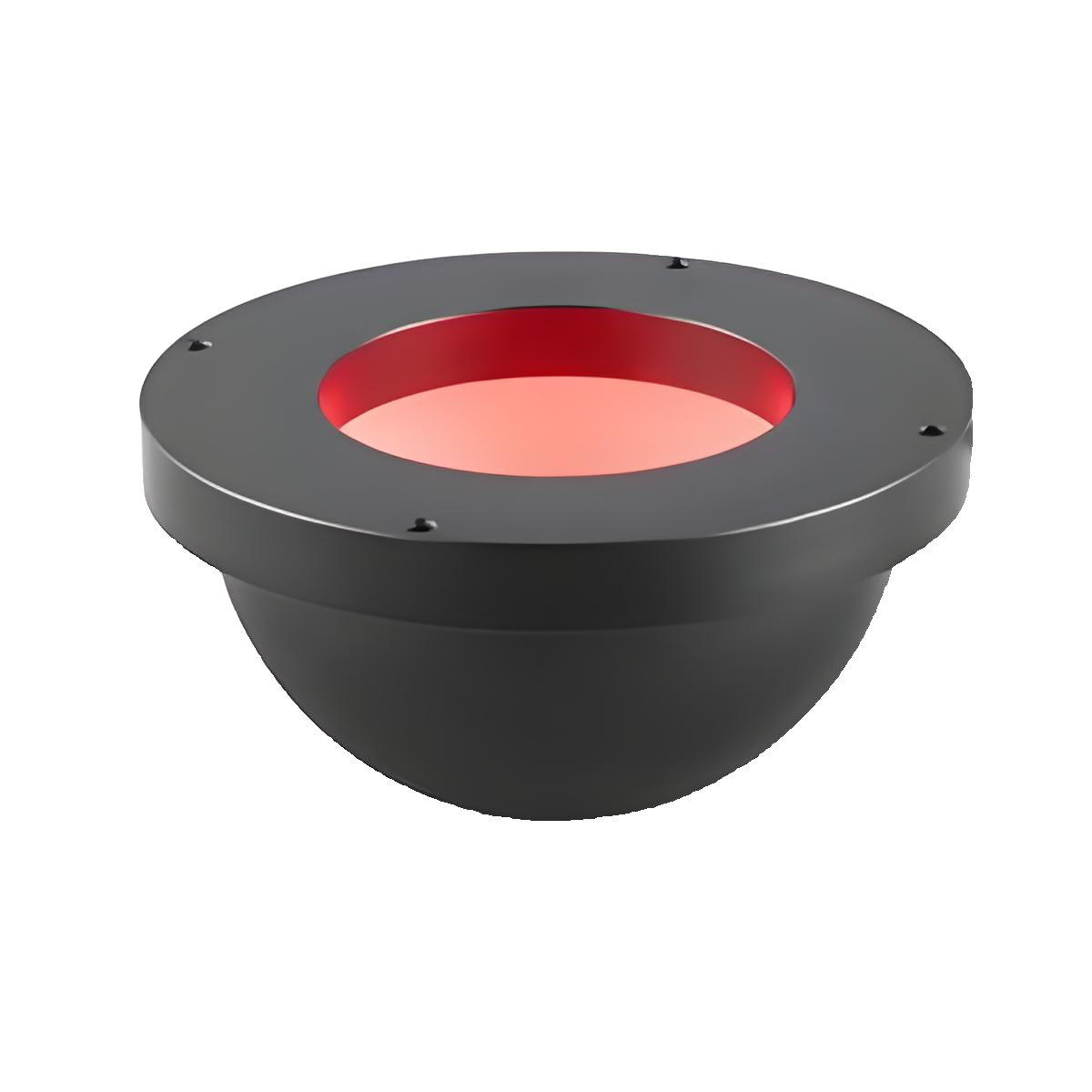
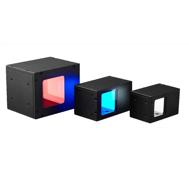
- Choose the right light source type, such as ring light, bar light, coaxial light, or backlight, based on the surface properties (reflective, absorbent, transparent) and color of the object.
- Decide on the color of the light source (white, red, blue, etc.) to enhance contrast between the object and the background.
- Consider the brightness and uniformity of the light source to meet the needs of different inspection scenarios.
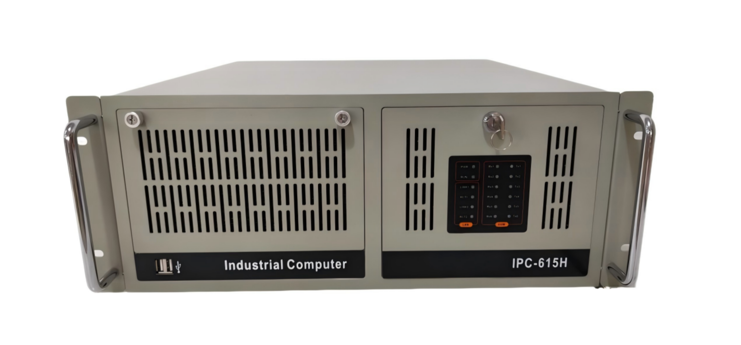
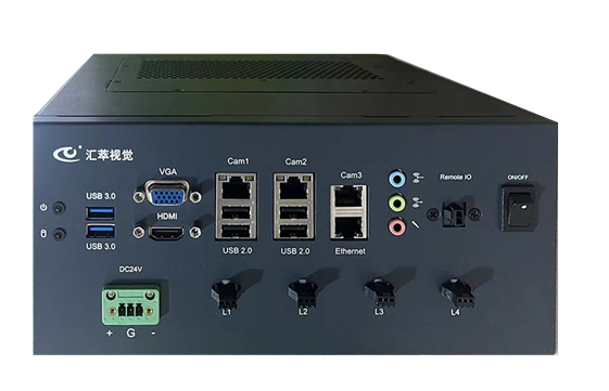
Frame Capture Card Selection:
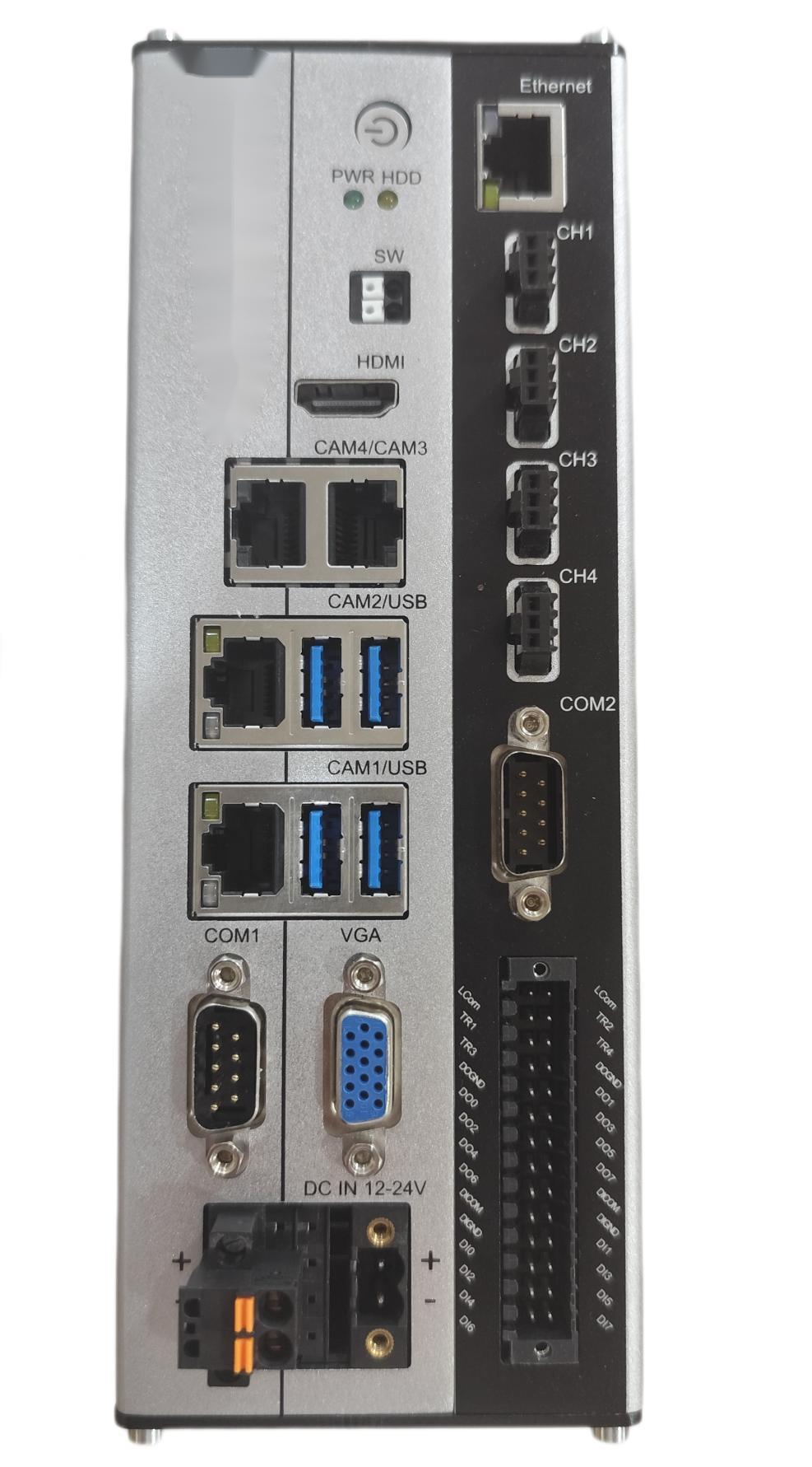
- Ensure the capture card is compatible with the camera’s interface, such as USB, GigE, Camera Link, etc.
- Choose a capture card with enough bandwidth to avoid data loss or delays based on the camera’s frame rate and resolution.
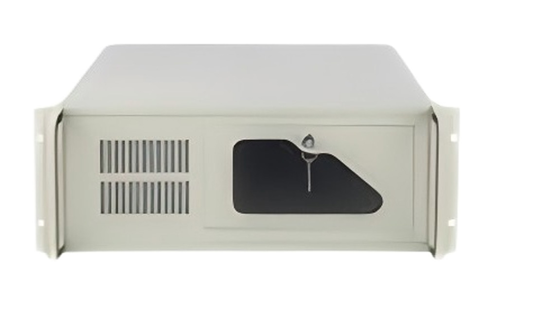
Hardware Installation:
- Follow the installation instructions for the camera, lens, and light source to correctly install and secure them in the appropriate position.
- Ensure solid connections between hardware components, and check that data and power cables are securely fastened.
3. Preliminary Setup and Connections
- Install the camera driver and related vision software, ensuring compatibility with the operating system.
- Set basic camera parameters in the software, such as exposure time (to control image brightness), gain (to amplify image signals), and frame rate (image capture speed).
- Connect the camera, light source, and computer, ensuring stable power supply and normal data transmission.
4. Lighting Tuning
- Turn on the light source and gradually adjust its position, angle, and height to ensure uniform illumination of the inspection area.
- For ring lights, adjust the inner and outer diameters to suit different sizes of inspection objects.
- For bar lights, change the direction and angle to highlight edges or features of the inspection object.
- Adjust the brightness of the light source by controlling the current or voltage to optimize the contrast between the object and the background in the image.
- Experiment with different light source colors to observe their effect on the inspection and select the color that best highlights defects or features.
5. Camera Tuning
- Fine-tune the camera’s focal length, ensuring the inspection area is clearly imaged without blurring or defocusing.
- Adjust the camera’s position and angle to capture the entire inspection area without image distortion.
- Set the white balance of the image to correct color deviations, making the image closer to its true color.
- Check the image noise level, and if necessary, adjust the gain and exposure time to reduce noise.
6. Image Acquisition and Evaluation
- Use the actual object to be inspected for image acquisition, capturing multiple sample images.
- Check the clarity of the images, ensuring details are clearly visible and edges are sharp.
- Evaluate the contrast of the image, checking if the difference between the object and the background is obvious and if defects are easily identifiable.
- Review the brightness uniformity of the image to ensure consistent brightness across the inspection area, with no significant light or dark spots.
- Analyze the color accuracy of the image to ensure it accurately reflects the characteristics of the object.
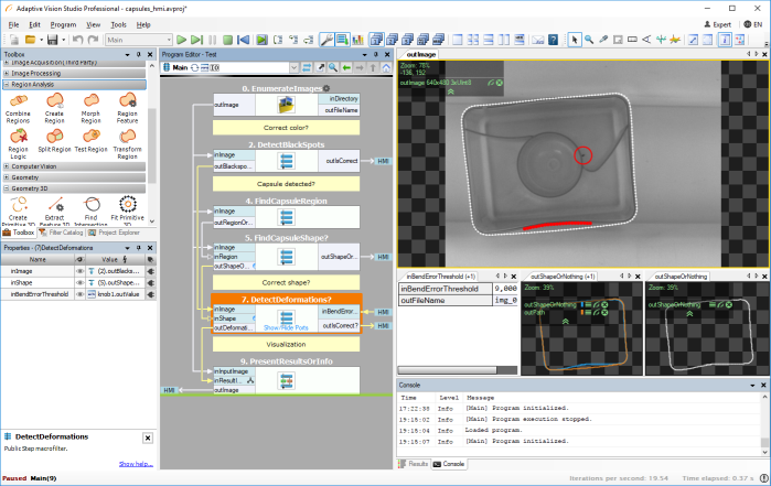
7. Algorithm Selection and Configuration
- Choose the appropriate visual inspection algorithm based on the inspection task:
- For shape and position detection, template matching algorithms can be used.
- For surface defect detection, edge detection or blob analysis algorithms can be applied.
- For more complex inspection tasks or those requiring classification, consider using deep learning algorithms like convolutional neural networks (CNN).
- Configure parameters for the selected algorithm, such as setting a matching threshold in template matching or adjusting edge strength thresholds in edge detection.
- For different algorithms, perform preliminary training and learning, using known sample data to optimize the algorithm’s performance.
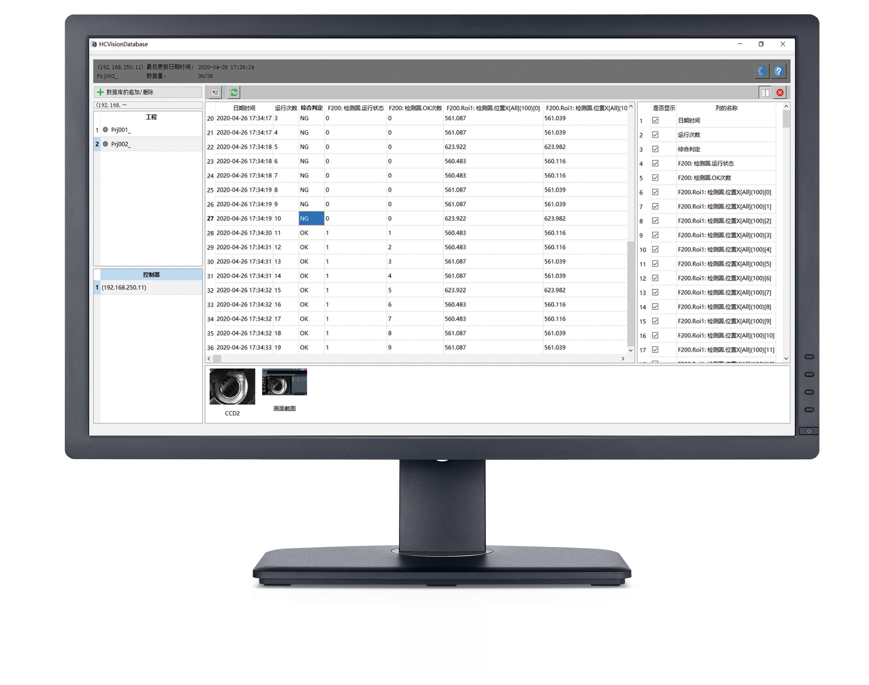
8. Software Interface and Operation Setup
- Design an intuitive and simple software interface for easy adjustments of parameters, viewing images, displaying results, etc.
- Divide the interface into functional areas, such as image acquisition, parameter settings, and result display.
- Set up functions for image zooming, panning, and rotating for detailed image examination.
- Configure shortcut keys to improve operational efficiency, such as for one-click image capture or initiating detection.
- Provide real-time operational prompts and error messages to help operators quickly resolve issues.
9. Precision Calibration
- Use standard calibration tools or calibration pieces with known sizes and features for precision calibration.
- Compare inspection results with the actual values of the calibration pieces, adjusting algorithm parameters or hardware settings such as pixel size calibration for the camera or distortion correction for the lens.
- Perform multiple calibration tests to ensure the accuracy and repeatability of the inspection results within an acceptable error range.
10. Speed Optimization
- Analyze the execution time of the algorithm and optimize time-consuming steps.
- Use parallel computing technologies to accelerate image processing by utilizing multi-core CPUs or GPUs.
- Optimize the transmission and storage methods for image data to reduce processing time overhead.
- Based on actual needs, reduce image resolution or remove unnecessary processing steps, improving detection speed while ensuring accuracy.
11. Stability Testing
- Run the equipment continuously for a period, typically several hours or even days, to observe its long-term performance.
- Check for image acquisition stability, ensuring there’s no image loss, lag, or abnormal interruptions.
- Monitor the consistency of detection results, tracking false positives and missed defects.
- Check hardware metrics such as temperature and noise levels, ensuring the equipment functions normally over long periods without overheating or malfunctions.
12. Interference Testing
- Simulate changes in ambient lighting, such as transitioning from bright light to dim light, to observe the light source and camera's adaptability and whether the detection results are affected.
- Apply vibration interference to check the stability of hardware connections and image quality.
- Introduce electromagnetic interference to evaluate the equipment’s resistance to electromagnetic noise, ensuring data transmission and processing are not affected.
- Observe whether the equipment can operate normally and whether the detection results remain accurate and reliable under various interference conditions.
13. Batch Testing
- Prepare a large number of actual product samples, covering all possible cases, including qualified products and various types of unqualified products.
- Conduct continuous testing on this batch of samples and record the results.
- Calculate accuracy rate (number of correctly detected items/total number of items), false positive rate (number of qualified products incorrectly marked as unqualified/total number of qualified items), and false negative rate (number of unqualified products incorrectly marked as qualified/total number of unqualified items).
- Analyze error cases in the detection results to identify the causes of false positives and false negatives.
14. Result Analysis and Adjustment
- Evaluate whether the equipment’s performance meets the requirements based on the batch test’s statistical data and error case analysis.
- For false positives and false negatives, further adjust algorithm parameters and optimize light source and camera settings.
- Re-test and verify until the detection results meet the expected performance indicators.
- Conduct another round of stability and interference testing on the adjusted equipment to ensure performance stability and reliability.
15. Training and Documentation
- Provide comprehensive training for operators, covering the basic principles of the equipment, operational processes, common issues, etc.
- Offer detailed operation manuals and maintenance guides for operators to refer to at any time.
- Record all key parameters, settings, issues, and solutions from the tuning process to form a complete set of tuning documentation.
- Include hardware configuration information, software versions, and algorithm parameters to provide reference for future equipment maintenance, upgrades, and troubleshooting.
16. Final Acceptance
- Invite the customer or stakeholders to conduct a final acceptance test of the debugged equipment.
- Demonstrate the equipment’s performance under various test conditions, including precision, speed, stability, and resistance to interference.
- Provide a report and data analysis from the batch tests, proving that the equipment meets the project’s initial requirements.
- Make final adjustments and refinements to the equipment based on the acceptance results, ensuring customer satisfaction before delivering the equipment for use.
It’s important to note that throughout the tuning process, steps and methods should be flexibly adjusted according to the actual situation to achieve the best visual inspection results.